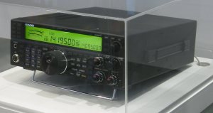
How does the new Yaesu FTdx1200 compare?

Yaesu introduces its new high performance HF-transceiver at the last Dayton Hamvention. It is, again, a wonderful piece of equipment. I have been using Yaesu’s FT-450 entry level rig for many years now, with much pleasure. It packs a lot of functionality and performance in a small and convenient package and I just love it.

yaesu-ftdx-1200

So how about the new FTdx1200?

The exterior of the new 1200 looks very much like last year’s FTdx3000. In fact, I had a hard time finding the differences. The color-LCD of the FTdx1200 is a bit larger (4.3in against the 3.5in of the 3000) and the 3000 has a secondary display above the large tuning dial showing the currently selected frequency.

Comparing the specifications of the FTdx3000 vs. FTdx1200 shows the two rigs are also very similar on the inside also. Both cover all the ham bands between 160 and 6 meters and both feature general coverage receiver range (30 kHz ~ 56 MHz). Sensitivity and selectivity is almost identical, with a small advantage for the newer FTdx1200. The FTdx1200 also features a more advanced receiver, with an extra IF-stage at 24 kHz (!) for AM and FM reception. Both rigs come with a 32-bit DSP processor, allowing you to tune IF-width and -shift to find those tiny signals amidst the noise and pileups.

That leaves only the prices to be compared. Currently, the FTdx3000 is listed for USD 2600 and the FTdx1200 goes for as little as USD 1900. I somehow get the feeling Yaesu has just out-priced its own stock. If you can live without the secondary display, the new FTdx1200 seems like a very sensible choice.

73!

Note: as PD0AC points out, you may need to purchase the USD 220.- optional USB interface unit to be able to update the firmware. Seems odd to me, if this is in fact true.

Published in: on June 5, 2013 at 8:05 pm  Comments (3)  
Tags: , , , , ,

Learning CW, military style

Published in: on October 12, 2009 at 6:55 am  Leave a Comment  
Tags: ,

Arduino “Hello World”

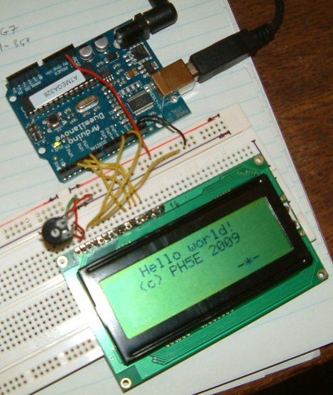
I got my Arduino board in yesterday. The first demo I’ve created is a small “Hello World” application that writes to an LCD display. The display has a Hitachi HD44780 (compatible) driver, so the Arduino LiquidCrystal library can be used to control it. Its only a small program, the comments in the code should explain what’s going on.

Hello World

Arduino's Hello World


/*
The circuit:
* LCD RS pin to digital pin 12
* LCD Enable pin to digital pin 11
* LCD D4 pin to digital pin 5
* LCD D5 pin to digital pin 4
* LCD D6 pin to digital pin 3
* LCD D7 pin to digital pin 2
* 10K resistor:
* ends to +5V and ground
* wiper to LCD VO pin (pin 3)

For more information about the library, please visit:
http://www.arduino.cc/en/Tutorial/LiquidCrystal
*/

// include the library code:
#include

// these constants won't change. But you can change the size of
// your LCD using them:
const int numRows = 4;
const int numCols = 20;

// initialize the library with the numbers of the interface pins
LiquidCrystal lcd(12, 11, 5, 4, 3, 2);

void setup() {
// set up the LCD's number of rows and columns:
lcd.begin(numRows, numCols);
lcd.clear();
delay(200);

// print hello world and my call
lcd.setCursor(4,0);
lcd.print("Hello world!");
lcd.setCursor(3,1);
lcd.print("(c) PH5E 2009");
}

void loop() {
// print small gadget on last line of display
for (int thisCol = 0; thisCol < numCols; thisCol++) {
lcd.setCursor(thisCol, 3);
lcd.print("-*-");
delay(500);
lcd.setCursor(thisCol, 3);
lcd.print(" ");
}
}

Published in: on August 27, 2009 at 8:35 am  Leave a Comment  
Tags:

Kenwood HF concept rig

Kenwood is working on a new HF rig. Not much is known at this moment, just a concept of what it might look like. My opinion? After the TS-2000 there was no way to make anything more ugly. Fortunatly Kenwood has also realised this and the new concept looks much, much better.

Kenwood concept HF

Kenwood concept HF

Update Aug. 2010: Kenwood has released the new rig under the name TS-590, specifications and images behind the link. According to Universal-Radio the rig should be available starting Oct. 2010.

Published in: on August 24, 2009 at 8:45 pm  Leave a Comment  
Tags:

Now THIS is a remote control!

Imagine a coffee table, with an image of your room as seen from above projected onto it. You see your TV, your lamps, your digital photo frame all projected onto the table. Now imagine you controlling those items by touching them on the image

Just watch the movie, and you’ll understand!

Published in: on August 20, 2009 at 11:42 am  Leave a Comment  
Tags:

The importance of good SWR is often overrated!

Let me start with the obvious: bad SWR can kill your transceiver! But there’s more to it than that. I often see and hear ham operators going to extreme lengths to get the SWR down to absolute perfect values. Even 1:1.1 is not acceptable to some!

Allow me to put this into perspective. An SWR ratio of 1:1 means 100% of the power of your transceiver get transfered to your antenna (or transfer line).  But a ratio of 1:2 doesn’t mean 50% is lost. It means 88.9% gets transfered, thus only 11% gets lost. And even with a ratio of 1:3 75% of your power still makes it to your antenna system. Unless your transmitting with huge amount of power, your transceiver will be able to cope perfectly fine with this.

To end the story, here’s a table with SWR ratios and their efficiencies:

SWR Radiated % Loss
1 100 ——-
1.3 98.3 .08dB
1.5 96 .18dB
1.8 91.8 .36dB
2 88.9 .51dB
2.5 81.6 .86dB
3 75 1.25dB
3.5 69.1 1.61dB
4 64 1.94dB
5 55.6 2.55dB
SWR   Radiated % Loss
1     100        none
1.3   98.3       0.08dB
1.5   96         0.18dB
1.8   91.8       0.36dB
2     88.9       0.51dB
2.5   81.6       0.86dB
3     75         1.25dB
3.5   69.1       1.61dB
4     64         1.94dB
5     55.6       2.55dB
Published in: on August 19, 2009 at 10:12 am  Leave a Comment  
Tags: , , ,

6m Inverted-V

My shack is located on the attic  of my house. The roof has a top angle of 90 degrees. This just begs for an inverted-v.

First, some calculations to determine the antenna dimensions. An inverted-v is a dipole hung under an angle, thus the total length of the 2 radials should be 1/2λ. I want my antenna to work optimal on 51MHz, the middle of the 6m band. The wavelength (λ) for 51MHz is 300/51=5.88m. One radial will thus be 5.88/4=1.47m (remember, 5.88m is λ, a dipole is 1/2λ and one radial is 1/2 the antenna, hence 5.88/4). We must also compensate for the fact that your transceiver sees a slightly different length depending on the angle of the V. When the angle is 90°, the compensation must be about 5% (shorter). At 130° the compensation is only about 2%, for a flat dipole (180°) no compensation is needed.

As my angle will be 90° I compensated 5%. This results in a radial length of 1.47×0.95=1.40m.

I cut 2 lengths of wire, slightly longer then the calculated length, hung them under an angle of 90°, connected my trusty Yaesu FT-450 and tuned to 51MHz. Turned out my SWR was 1:2.5, not bad, but not perfect. I cut a few centimeters from both radials and gave it another try. This time the SWR was down to 1:1.8, good enough for me!

I connected my coax cable directly to the radials of the inverted-v. In some cases it may be necessary to use a 1:1 balun or a choke filter. Experiment with this!

Published in: on August 19, 2009 at 9:59 am  Leave a Comment  
Tags: ,

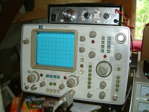
HP 1740A, 100MHz oscilloscope

HP 1740A 100MHz scope

HP 1740A 100MHz scope

A decent set of measuring devices should be present is every ham shack. I’ve bought me a 100MHz scope. It’s an oldy, dating from the late 1970’s or early 1980’s, but it’s still very usable.

The box on top of the scope is my U/I curve tracer, or component tester. It allows me to test diodes, transistors, resistors and capacitors. What is does is trace current versus voltage and display that on the scope.

Published in: on July 9, 2009 at 9:33 am  Leave a Comment  
Tags: ,

S-Meter – Ham Radio Site

Check out www.smeter.com, lots of valuable information about topics like receivers, antennas, frequencies, propagation, etc., etc., etc.

Published in: on July 8, 2009 at 2:41 pm  Leave a Comment  
Tags:

Sunspots are coming

Quote from space.com:

After one of the longest sunspot droughts in modern times, solar activity picked up quickly over the weekend.

A new group of sunspots developed, and while not dramatic by historic standards, the spots were the most significant in many months.

“This is the best sunspot I’ve seen in two years,” observer Michael Buxton of Ocean Beach, Calif., said on Spaceweather.com.

If the guys at space.com are right, we should be getting some better conditions soon. And it’s about time I’d say.

11-year sunspot cycle

11-year sunspot cycle

Original article can be found here

Published in: on July 8, 2009 at 12:07 pm  Leave a Comment  
Tags: